A battery energy storage system can have healthy cells and a capable inverter yet still miss its operating target. The usual cause is not one bad controller. It is a poor handoff between the battery management system, energy management system and power conversion system. BMS vs EMS vs PCS is therefore a question of control boundaries: the BMS protects the battery, the PCS moves electrical power, and the EMS decides when and why the system should charge or discharge.
BMS vs EMS vs PCS at a Glance
The fastest way to separate the three is to follow one dispatch command. The EMS requests 300 kW of discharge. The PCS converts DC battery power into grid-compatible AC power. The BMS checks cell voltage, temperature, current and state of charge, then permits, limits or blocks the request. None of the three can replace the other.
| System | Primary job | Typical data | Direct control |
| BMS | Protect battery cells and estimate battery state | Cell voltage, temperature, current, SOC, SOH | Contactors, current limits, alarms |
| PCS | Convert and regulate electrical power | DC voltage, AC voltage, frequency, power, faults | Charge/discharge current, active and reactive power |
| EMS | Schedule the whole energy system | Tariff, load, PV, meter data, forecasts, availability | Dispatch setpoints and operating modes |
What the Battery Management System Does
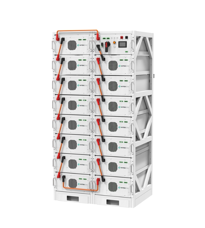
The BMS works closest to the cells. It reads individual cell voltages and temperatures, watches pack current, estimates state of charge and state of health, and opens contactors when operating limits are breached. Its protection logic is local and fast. A site controller should never override a BMS stop command.
Consider a rack with one module warming faster than the others. The EMS may still see a profitable peak-shaving window. The PCS may be ready to discharge. The BMS sees the temperature spread and lowers the allowable current. That limit must travel upstream before the EMS issues another setpoint. For a deeper view, read how a BMS protects battery performance.
What the Power Conversion System Does
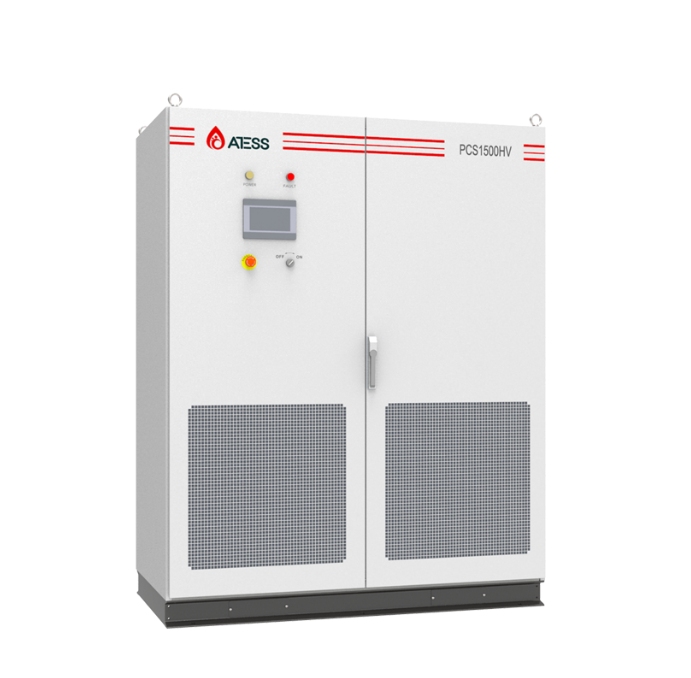
The PCS is the electrical bridge between the DC battery and the AC bus. It controls current, synchronizes with grid voltage and frequency, and follows active or reactive power commands. During charging it converts AC to DC. During discharge it reverses the flow. Conversion efficiency, overload time, harmonic performance and grid-code functions all sit within the PCS scope.
A 500 kWh battery paired with a 100 kW PCS is roughly a five-hour system at full power. The same battery paired with a 250 kW PCS is closer to two hours. The battery stores energy; the PCS sets the rate at which much of that energy can move. The site design must check both numbers rather than treating kWh as a complete system rating.
What the Energy Management System Does
The EMS sits above the equipment layer. It combines meter readings, load forecasts, solar output, electricity prices, reserve targets and equipment availability. It then chooses an operating mode and sends power setpoints. Good EMS logic also respects BMS limits, PCS status, transformer capacity and the point-of-connection limit.
At a factory, for example, demand may rise from 720 kW to 910 kW at 14:15. If the contracted limit is 800 kW, the EMS requests about 110 kW of discharge. The PCS delivers that power. If the BMS reports only 80 kW available because the battery is cold or near its lower SOC limit, the EMS must accept the reduced ceiling.
How the Three Controllers Exchange Commands
A practical control chain has four steps:
The EMS calculates a charge or discharge setpoint from the site objective.
The PCS checks that the command fits its voltage, current and grid limits.
The BMS publishes charge and discharge limits based on cell conditions.
The EMS records the delivered power and adjusts the next command.
Communication commonly uses industrial protocols, but the protocol name alone does not prove compatibility. The integrator needs a signal list, units, update rates, alarm priorities, timeout behavior and a clear rule for stale data. One wrong scale factor can turn a 100 kW request into 1,000 kW.
Common Integration Failures
SOC values use different scales, such as 0-1 in one controller and 0-100 in another.
The EMS keeps dispatching after a communications timeout.
The PCS fault resets automatically while the BMS fault needs inspection.
Charge limits update too slowly during a rapid temperature change.
Site meters and PCS meters use opposite import/export signs.
The operator can see an alarm but cannot trace which device created it.
How to Test the Control Chain Before Handover
Point-to-point testing should begin before the battery is asked to cycle. Engineers first compare every important signal against the approved register: value, unit, sign, scale and timestamp. A live current reading of 125 A must appear as 125 A at the BMS gateway, PCS controller and EMS screen. Alarm states need the same check. A label that changes meaning between systems can waste hours during commissioning.
Functional tests then place the system in normal and abnormal states. The team can lower the simulated discharge limit, interrupt one communications link, create a meter mismatch and request power above the PCS rating. Expected results should be written before the test. For example, a lost BMS link should block new dispatch, while a lost tariff feed may allow the EMS to fall back to a conservative fixed schedule.
Finally, run a short charge and discharge sequence while recording setpoint, actual power, SOC, allowable power and alarms on one timeline. A five-second delay may be acceptable for an operator dashboard but too slow for a control loop. The acceptance report should list each test, expected response, observed response, owner and closure date.
LIB System Advantages for Coordinated Control
Lithium iron phosphate battery systems suit repeat-cycling projects because modular racks, cell-level monitoring and defined operating limits can be integrated into a layered control scheme. The exact values depend on the selected configuration, so an RFQ should request verified project data rather than generic claims.
| Design item | Buyer should request | Why it matters |
| BMS limits | Dynamic charge/discharge current and fault states | Keeps EMS commands inside cell limits |
| PCS interface | Power range, ramp rate, reactive power and fault map | Defines electrical response |
| EMS logic | Modes, priorities, reserve SOC and fallback behavior | Defines the business result |
| Communications | Protocol map, update rate and timeout action | Prevents stale or misread commands |
| Data history | SOC, SOH, alarms, power and temperature logs | Supports service and warranty review |
HITEK ENERGY provides energy storage system solutions for commercial and industrial applications. Buyers can also review the company’s battery information when preparing controller and monitoring requirements.
Questions to Put in a BESS RFQ
Who owns the master dispatch command?
What happens when EMS-to-PCS communication is lost?
Which BMS limits are available to the EMS in real time?
Can operators export one-second and 15-minute data?
Who supplies the final signal list and performs point-to-point testing?
Which alarms require a site visit before reset?
Conclusie
BMS vs EMS vs PCS is not a contest between three controllers. Each has a different authority. The BMS protects cells, the PCS controls power conversion, and the EMS turns a site goal into dispatch commands. A reliable BESS makes those boundaries visible in drawings, signal lists, alarm rules and acceptance tests. That work prevents many commissioning delays and gives the operator data that can actually explain system behavior.
Veelgestelde vragen
Can a BESS run without an EMS?
A small system may run fixed PCS modes without a site EMS, but multi-use commercial projects normally need supervisory scheduling, meter feedback and reserve management.
Does the BMS control the PCS?
The BMS usually sends permissible current or power limits and stop signals. The PCS controls conversion within those limits, while the EMS supplies the operating setpoint.
What is the difference between BMS and EMS data?
BMS data describes battery condition at cell, module and rack level. EMS data combines equipment status with site load, tariffs, solar output and operating targets.
Who should test BMS EMS and PCS integration?
The system integrator should own end-to-end testing with participation from the battery, PCS, EMS and EPC teams. The test should include lost communications and abnormal limits.
What information is needed for a controller quotation?
Share the single-line diagram, battery and PCS ratings, use cases, metering points, required protocols, grid rules and expected remote-monitoring scope.
Project teams can send control requirements through the HITEK ENERGY contact page.
HITEKESS ENERGY STORAGE SYSTEMS ON HOT SALE
- Hitek 100kw 200kwh Ess Outdoor Cabinet 380V 3phase 50kw 100kw PCS Inverter Battery Storage System with 100kwh 200kwh 229kwh Lithium Ion Battery Backup
Model: HTAC-100/200-OD
- Hitek 3 Phase off Grid Hybrid Complete Set Solar Photovoltaic System 150kw 100kw 250 Kw Solar Power Storage System for Farm
Model: HT250KW-HY
- Zuid-Afrika Offgrid Hybrid Zonne-System150kw 120kw 100kw 50kw 30kw 50kwh 100kwh Zonne-Energiesysteem met LiFePO4 Batterij Backup
Model: HT50KW-HY
- Hitek 500kw on off Grid Solar Energy System 350kw 400kw 600kw 800kw Hybrid Solar Photovoltaic Storage System High Voltage 3 Phase Solar Energy System
Model: HT500KW-HY
- Renewable Energy Hitek Best 250kw Inverter off Grid on Grid Hybrid 50kw 100kw 150 Kw 250kw Complete Solar Power System Cost All in One Solar Panels System
Model: HT250KW-HY